|
iQ Valves offers a wide range and variety of proportional valves. Choosing the right
valve for your application is important to give you better control over the valve
and your process. |
| |
| Valve selection is based on the pressure differential the valve will see and maximum
flow expected at that pressure. Considering these parameters iQ Valves offers three
different categories of valves: |
| |
1. Miniature valves for ultra low flows вҖ“ IQ Nano
2. Mid range
valves for moderate flows вҖ“ IQ Mini, IQ Coral
3. Standard valves for high flows вҖ“ Standard PFCV |
| |
|
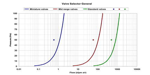
The following four charts will guide you in selecting a valve (based on air as the
medium). Each of them is divided into different sections by dividing lines. These
sections correspond to the category of valve in chart 1 and give the required orifice
sizes in charts 2, 3 and 4. Charts 2, 3 and 4 give the required orifice size in
Miniature (Chart #2), Midrange (Chart #3) and Standard valve (Chart #4) respectively. |
|
|
|
The following examples illustrate valve selection using the charts. |
|
|
|
Example 1: Pressure differential across the valve: 50 Psi |
|
Medium: Air |
|
Maximum required flow: 0.6 slpm |
|
|
|
To find the valve category
use chart 1. Locate a point in chart 1 with pressure and maximum required flow as
the co-ordinates (Note Chart 1 has flow in logarithmic scale). In this example the
point (with 50 psi and 0.6 slpm as co-ordinates) is in left most section on the
chart, which corresponds to Miniature valves. |
| |
 |
 Chart1 Chart1
|
|
|
|
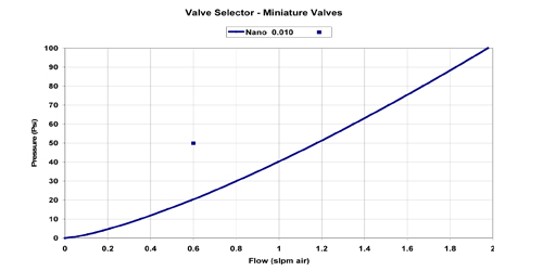
To find the required orifice
size in the Miniature valve use chart 2. The point in this chart is in the 0.010
inch orifice size section. Thus appropriate valve for this application is 0.010
inch orifice size Miniature valve. |
|
|
 |
 Chart2 Chart2
|
|
|
|
Example 2: Pressure differential across the valve: 50 Psi |
|
Medium:
Air |
|
Maximum
required flow: 60 slpm |
|
style="text-align:justify; padding-left:6px; padding-right:6px;"
To find the proper category
of the valve use chart 1. In this example the point (with 50 psi and 60 slpm as
co-ordinates) is in middle section on the chart, which corresponds to Midrange valve. |
|
|
|
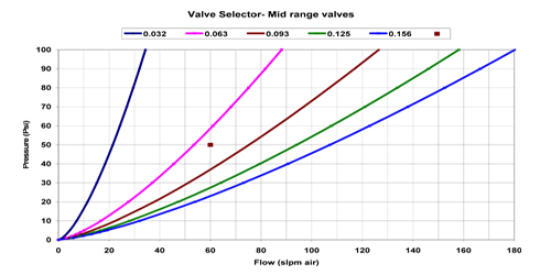
To find the required orifice
size in the Midrange valve use chart 3. The point in this chart is in the 0.093
inch orifice size section. Thus appropriate valve for this application is 0.093
inch orifice size Midrange valve. |
|
|
 |
 Chart3 Chart3
|
|
|
|
[For the same pressure differential of 50 psi and maximum flow requirement of 100
slpm the point will land in 0.156 orifice area, so the valve for this application
will be 0.156 orifice size Midrange valve. Another example would be for 90 psi pressure
and maximum required flow of 60 slpm the point will land in 0.062 orifice range,
so the valve for this application will be 0.062 orifice size Midrange valve.] |
|
|
|
Example 3: Pressure differential across the valve: 50 Psi |
|
Medium:
Air |
|
Maximum
required flow: 500 slpm |
|
To find the valve category
use chart 1. In this example the point (with 50 psi and 500 slpm as co-ordinates)
corresponds to Standard valve. |
|
|
|
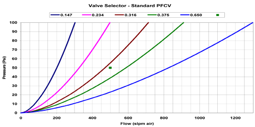
To find the required orifice
size in the standard valve use chart 4. The point in this chart is in the 0.375
inch orifice size section. Thus appropriate valve for this application is 0.375
inch orifice size Standard valve. |
|
|
 |
 Chart4 Chart4
|
|
|
|
[For the same pressure differential of 50 psi and maximum flow requirement of 700
slpm the point will land in 0.650 orifice area, so the valve for this application
will be 0.650 orifice size Standard valve. For 90 psi pressure and maximum required
flow of 500 slpm the point will land in 0.316 orifice area, so the valve for this
application will be 0.316 orifice size Standard valve.] |
|
|
| Proportional Valve Product Line
|
| Top |
|
|